
- #Icom ic 7800 power manuals#
- #Icom ic 7800 power pdf#
- #Icom ic 7800 power install#
- #Icom ic 7800 power mod#
Condition:: Brand New: A new, unread, unused book in perfect condition with no missing or damaged pages. but they are worth it! High Quality Paper. Very Large Manual! Very Nice Manual! Manual is Printed on 8 1/2" X 11" 32 LB. High Quality Icom IC-7800 Instruction Manual w/32Lb (IN COLOR) *PRINTED Printed 2400dpi. High Quality Icom IC-7800 Instruction Manual w/32Lb *PRINTED IN COLOR

#Icom ic 7800 power manuals#
After this modification, there will be no band edge beeps if you had them turned on before, so be careful not to operate out of your band segment.Įnjoy your new General Coverage Transmit IC7800.High Quality Icom IC-7800 Instruction Manual w/32Lb *PRINTED IN COLOR Manuals & Magazines Parts & Accessories Reinstall the 4 small front panel mounting screws(2 per side) and reinstall the bottom and top covers. Position the front panel unit back down into position in its proper place and then check to make certain that the connectors which connect to the front panel unit and to the logic unit are securely plugged in properly.
#Icom ic 7800 power install#
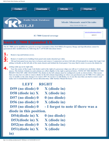
If you have to add diodes, try to use the ones that you had to remove(and make sure to install them in the correct direction-they ARE Surface Mount Devices):ĭ55 (no diode) 0 - I forgot to note if there was a diode in this position. USA radios are easy to modify as the only change is to remove D57. This means that you may have to add or remove diodes in the left column depending on where you purchased your IC7800. NONE OF THE DIODES IN THE RIGHT COLUMN ARE CHANGED!! The diodes in the left column must be configured exactly as shown below. The bottom 4 diodes in each column are offset slightly to the right as pictured below. Near the center of the Logic Unit (below and to the right of a processor chip) you will see 2 vertical rows of diodes / diode spaces. You may find it easier to access the diodes by setting radio up on its right side. Tilt up front panel(you may have to loosen and remove 2 connectors on lower left side of front panel) to expose the Logic Unit sitting vertically on the left side of the main chassis unit behind the front panel. Remove 4 small screws holding front panel onto main chassis(2 per side). The IC-7800 can be modified for general coverage transmit(1.6 thru 54.0 MHZ) (Frequency Range and Specifications cannot be guaranteed after modification) by following the CAP/MARS directions below: Icom IC-7800 (IC 7800 IC7800) technical specifications

Icom IC-7800 (IC 7800 IC7800) technical specifications :
#Icom ic 7800 power mod#
Icom IC-7800 (IC 7800 IC7800) General Coverage Transmit Mod
#Icom ic 7800 power pdf#
PDF Adjusments Procedures Manual with schematics for Icom IC-7800 (IC 7800 IC7800) : Icom IC 7800 Adjustment Procedures Manual PDF User Manual for Icom IC-7800 : Icom IC 7800 Instruction Manual Programming software for Icom IC-7800 (IC 7800 IC7800) : Programming interface schematics for Icom:


 0 kommentar(er)
